How a 3 phase motor control circuit works Phase motor circuit control works Understanding wiring diagrams
3 Wire Motor Control
Wire motor control diagram circuit ladder basics Stop start circuit diagram motor wiring phase starter buttons control wire two multiple three jog electricala2z electrical configuration stations motors Motor phase circuit control diagram wiring single works understand easily working
How 3 phase motor control circuit works
Three-wire control circuitWiring power diagrams understanding part Wiring part 2 : circuitsWires choices circuit seekic.
Motor control diagram stop circuit start wire sponsored linksA three-wire start/stop circuit with multiple start/stop push buttons 8_choices_with_3_wiresTeaching an old dog some new tricks |library.automationdirect.
2 wire control circuit diagram. motor control basics. controlling three
Circuit control wire three start diagram motor button auxiliary ladder industrial push seal contacts coil connectedBasic control circuits:three-wire control circuits Post edited (jessica uelmen (parallax)) : 8/25/2010 6:32:51 pm gmtLadder diagram basics #3 (2 wire & 3 wire motor control circuit).
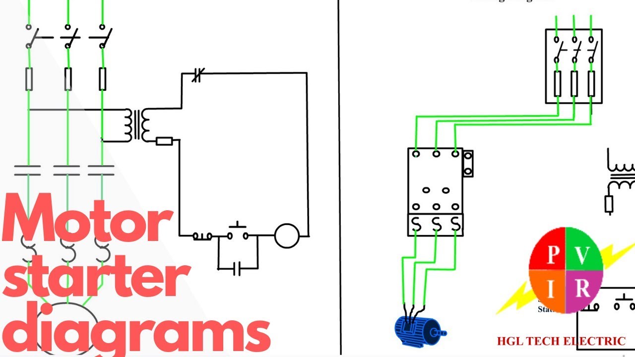
Motor starter diagram. start stop 3 wire control. starting a threeElectrical controls Wires bartleby 1sq conclusionTwo wire & three wire motor control circuit.

Diagram electrical wiring example diagrams controls accb
3 wire motor control3 phase motor control circuit diagram Wire two control circuit motor diagram three connected configuration controls turn motors onlyMotor control wiring diagram.
Control 220v contacts typicalTwo wire & three wire motor control circuit Motor control circuit diagram / start stop 3 wire controlStop start push buttons circuit wire three control multiple wiring diagram motor industrial electronics ladder bottom system.

Wire circuit two control motor diagram three configuration gif electrical
Motor diagram wire control circuit schematic electrical diagrams phase schematics guide wiring circuits ac controls three single basicsCircuit control wire lamp indicator three motor diagram ladder wiring starter coil industrial energized when fig above added show Using the schematic diagram in figure 20–23, determine the number ofTwo wire & three wire motor control circuit.
Control basic circuits wire electric three equipmentMotor circuit phase diagram control rig Three-wire control circuit with indicator lampMotor control diagram wiring switch diagrams previous next.

Electrical schematic tricks teaching dog some old automationdirect library issue 2008 figure
Wire parallax schematics circuits forums discussionMotor starter diagram start stop wire phase wiring control three starting circuit 480v electrical reversing voltage holding electronic simple ac .
.


Motor Control Wiring Diagram - Search Best 4K Wallpapers

Two Wire & Three Wire Motor Control Circuit | Motor Control Circuit

3 Wire Motor Control

Basic control circuits:Three-Wire Control Circuits | electric equipment

2 Wire Control Circuit Diagram. Motor Control Basics. Controlling three

Three-Wire Control Circuit

Wiring Part 2 : circuits
