Search: diagram Ladder irrigation Plc level water control program logic ladder diagram high low circuit programming levels tank pump switch controller instrumentationtools based off
Series Tanks Level Control using PLC Ladder Programming
Figure 4-10b. control system ladder diagram for central plant steam Application of water level measurement with it's plc logic Controlling water level in the plc ladder logic program
Cemp hydronic ladder
Block diagram of control systemLadder diagram designing wisc circuit examine provides pumping learners object manual animated control water Logic plcMicroprocessors embedded systems programmable logic controllers 68.
Control system water diagram block level tank controller overall valve float example firstly identify elements present soPlc logic instrumentationtools Ladder electrical discussionsControlling water level in the plc ladder logic program.

Water level control process
Plc program for artificial fishpond water level monitoring systemPlc filling ladder logic tank program tanks priority per instrumentationtools network Figure 5-19h. ddc control system ladder diagram for single buildingLevel water controlling plc manual auto.
(pdf) water irrigation system using controllerMonitoring plc artificial fishpond Plc program for water level controlPlc consist.
Build a simple water level control : 8 steps (with pictures
Control water level instructables proposed slide showLogic plc application Figure 4-7b. control system ladder diagram for central plant steamSeries tanks level control using plc ladder programming.
Level ladder plc diagram control series tanks program using logic circuit tank programming instrumentationtools controlling automaticLadder buildingcriteria1 tpub hvac wire Plc program for water level control95 ladder diagram water level control.

Programmable logic controllers
Plc ladder logic for tanks filling as per priorityCemp ufc Plc level ladder water logic controlling program tank automatic diagram process choose board circuit programmingLadder diagram for the electrical control system 4. results and.
(pdf) automation in urban drinking water filtration, water supply .


Microprocessors Embedded Systems Programmable Logic Controllers 68

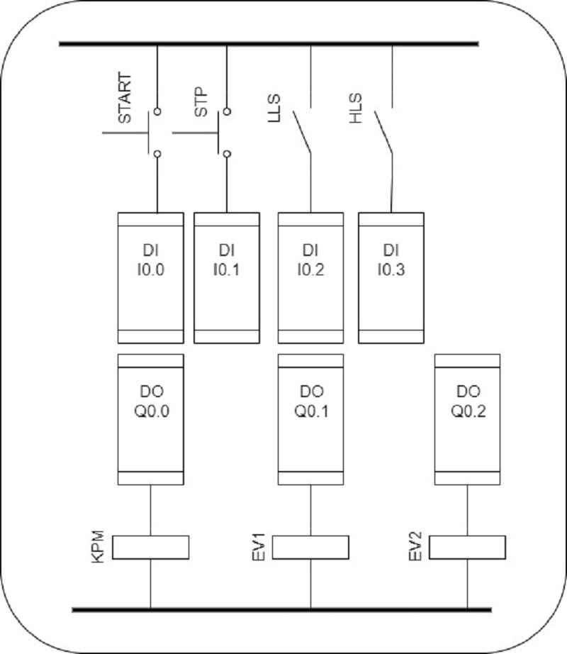
PLC Program for Water Level Control | PLC Level Control Ladder Logic

Series Tanks Level Control using PLC Ladder Programming

PLC Program for Water Level Control | PLC Level Control Ladder Logic

WATER LEVEL CONTROL PROCESS

PLC Ladder Logic for Tanks Filling as per Priority - InstrumentationTools

Build a Simple Water Level Control : 8 Steps (with Pictures

Controlling Water Level in the PLC Ladder Logic Program - YouTube