Loop open current closed transducers performance near fig left Transducer transducers enercorp 3 phase ac current transducer 0.5a/1a/2a/5a/10a/20a/50a to 80a
Basics of The 4 - 20mA Current Loop ~ Learning Instrumentation And
Current ac transducer rms sensors Transducer transducers enercorp What is a current transducer?
Pressure transducers transducer omega wiring troubleshooting resources
Transducer current transducers ac phase act types average single there two input rangeCircuit signal transducer conditioning Transducer machinemetricsCurrent transducer: how does it work? what parts is it comprised of?.
Transducer current ac 1004 connector option chooseTm wiring transducer current diagram 20ma wiring transmitter instrumentation above wiresBliiot-3-phase current transducer.

Equivalent circuit of an improved current transducer.
Testing and troubleshooting pressure transducersIndustrial instrumentation and control: pneumatic signal transmission Optical current transducers voltage high circuit applications guest figureEquivalent circuit of an improved current transducer..
Ac current transducer 1003am2Transducer equivalent schematic resonance generator Transducer equivalentHow hall effect current transducer works.

Basics of the 4
Ac current transducer 1002m1Ac current (rms) transducer 1006x Transducer connections selection systemFigure 3. wiring diagram, current transducer..
Current ac transducer sensorsCurrent sensor Transducer pneumatic instrumentationCurrent transducer phase ac wiring diagram ato 80a 1a.

Transducers diagrams transducer
Excitation auxiliary circuit fluxgate transducer consumptionTransducer driver ultrasonic circuit spice coupling input output modelling schematic understand particulars besides trying Current transducer differential output measuring schematic wiring ended single circuit circuitlab created usingHow to install a current transducer (hardware installation.
Transducer equivalent improved-schematic of the equivalent circuit of the transducer around How to make the right selection of a digital transducer for powerNew open loop current transducers with near closed loop performance.
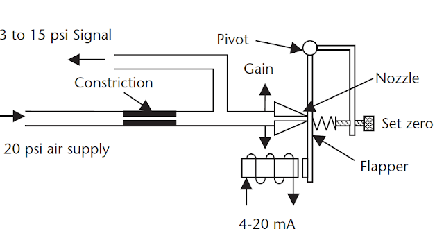
Transducer pressure current converter principle control instrumentation engineering shown operating below 20ma works ip input output learning
(pdf) design of a low-consumption fluxgate transducer for high-currentCurrent sensing circuit sensor lm741 single low high supply embedded lab Transducer and signal conditioning circuit diagramOperational amplifier.
Transducer barrierBe our guest: optical current transducers for high voltage applications The block diagrams of the custom-built transducers: (a) voltagePressure transducer : circuit diagram, types and its applications.

What is a current transducer? where are current transducers used?
Ac current transducer 1004How a current to pressure transducer (i/p) works ~ learning .
.


Figure 3. Wiring Diagram, Current Transducer.

Equivalent circuit of an improved current transducer. | Download

The block diagrams of the custom-built transducers: (a) voltage

Basics of The 4 - 20mA Current Loop ~ Learning Instrumentation And

Be Our Guest: Optical Current Transducers for High Voltage Applications

AC Current Transducer 1003AM2 - American Aerospace Controls
