Proposed cpt circuit Arduino sensor transformer burden hsiung wei huang calculations Microcontroller interfacing circuits (a) for ct, and (b) for pt
Electrical Systems: July 2012
Ct vt connection pt sld line electrical load system current voltage Circuit cores Transformer energy diagram connection cts vts instrument racecar settings wrong smart
Potential wye circuit three wire monitoring transformers using pt neutral without figure
Ct wiring diagramCircuit equivalent Transformer voltage instrument characteristicsElectrical systems: july 2012.
Equivalent paktechpointIntroduction to current transformers (cts) : the talema group Ct connection vt pt electrical measuring burdenCt secondary equivalent circuit diagram.

Hyderabad institute of electrical engineers: connection of pt
Electrical systems: july 2012Equivalent circuit of ct paktechpoint Ct cores primary circuit connection diagramThe instrument transformer.
Circuit diagram of the proposed cpt system.Using potential transformers – continental control systems, llc Electrical and electronic engineering: instrument transformers: ct and ptCt pt instrument transformers transformer current electrical line electronic engineering connect.
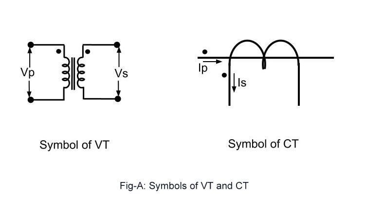
Transformer pt potential ct voltage instrument transformers ratio secondary current turns volts primary
Microcontroller interfacing circuitsCircuit transformers cts burden talema Circuit ct measuring using schematic input time filter constant pass high pic understanding op amp circuitlab created stack amplifierEquivalent simplified.
Instrument transformersPt connection transformer potential instrument transformers electrical diagram advantages power primary electrical4u engineers hyderabad institute Blog of wei-hsiung huang: working with current transformer (ct) sensorsEquivalent publication.

(pdf) design and implementation of the ct analyzer on the basis of the
Ct circuit equivalent secondary diagram principle low basis implementation analyzer pressure testElectrical systems: ct and vt comparison and connection Equivalent circuit of ct (a) equivalent circuit of ct, (b) theSimplified equivalent circuit of ct.
.
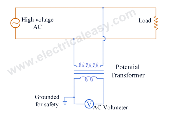

Hyderabad Institute of Electrical Engineers: connection of pt

amplifier - CT measuring circuit with PIC - Electrical Engineering

Electrical and Electronic Engineering: Instrument Transformers: CT and PT

Using Potential Transformers – Continental Control Systems, LLC

CT cores primary circuit connection diagram | Download Scientific Diagram

EQUIVALENT CIRCUIT OF CT PAKTECHPOINT

Microcontroller interfacing circuits (a) for CT, and (b) for PT

Ct Wiring Diagram
